Concept, Working Principle and Application Guide
In modern data centers, industrial plants and critical power systems, a single utility source is no longer enough to meet “zero-downtime” expectations. To keep servers, control systems and sensitive loads running during a power disturbance, dual-source or multi-source power architectures are widely used.
At the heart of many of these architectures is the 3-phase 630A Static Transfer Switch (STS) – a device designed to transfer a load between two independent power sources in just a few milliseconds.
1. What is a 3-phase 630A Static Transfer Switch?
A 3-phase 630A STS is an electronic switching device that uses high-power semiconductors (thyristors or IGBTs) to automatically transfer a three-phase load between two AC sources. Key characteristics:
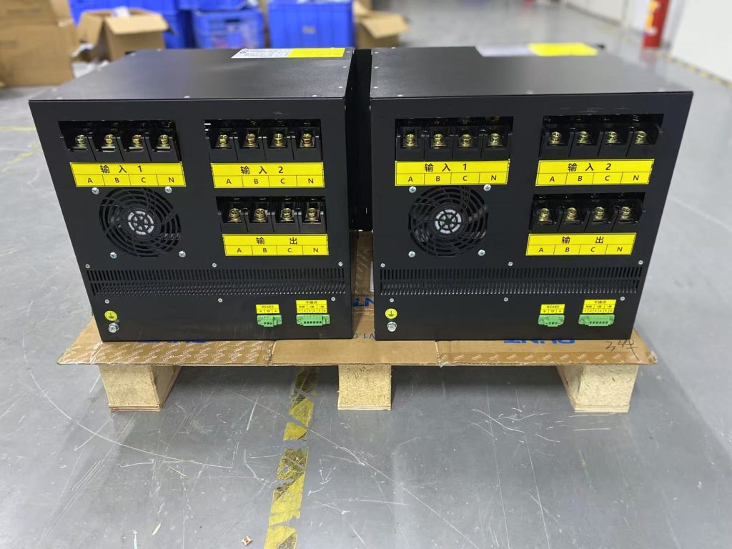
- Two inputs: Source 1 (often the preferred or “normal” source) and Source 2 (backup source, UPS output, generator, etc.)
- One output: Feeds a critical load bus or distribution panel
- Rated current 630A: Suitable for roughly 400–500 kVA at 400 V (depending on power factor and load type)
- Static (solid-state) transfer: No mechanical contacts; switching is electronic and extremely fast
In simple terms, when the preferred source becomes unacceptable, the STS moves the load to the alternate source in a few milliseconds, so most IT or electronic loads never shut down or reboot.
2. How does a 3-phase STS work?
2.1 Continuous monitoring of both sources
The STS continuously measures electrical parameters of each input:
- Voltage magnitude (over-/under-voltage)
- Frequency deviation
- Phase sequence and phase angle difference
- Sometimes harmonic distortion and other power quality indicators, depending on model
2.2 Static power devices and transfer logic
- Each source is connected to the output through a dedicated set of power semiconductors.
- In normal operation, only one path is conducted (e.g., Source 1). The other path is blocked.
- When the controller detects that Source 1 is out of tolerance or has failed, it turns off the semiconductors of Source 1 and turns on those of Source 2, typically at or near a voltage zero-crossing to minimize stress.
2.3 Transfer time
Typical STS transfer times are 2–4 ms, which is:
- Much faster than most IT loads’ ride-through capability (often 10 ms or more)
- Comparable to, or faster than, the transfer in many line-interactive or offline UPS systems
For the load, this appears only as a slight voltage dip, without shutdown or reboot.
2.4 Priority and operating modes
Most STSs allow you to configure operating logic, for example:
- Preferred source mode: Always use Source 1 when it is healthy; transfer to Source 2 only during a fault, and automatically re-transfer back when Source 1 recovers and stabilizes.
- No-priority or backup-preferred modes: The STS stays on whichever source is healthy first, or follows a custom policy to minimize the number of transfers or optimize generator runtime.
3. Typical applications of a 3-phase 630A STS
3.1 Data centers and cloud facilities
- Dual utility feeds or dual UPS systems (A/B feeds)
- A 3-phase, 630A STS is installed upstream of row distribution panels or PDUs
- Ensures servers, storage and network equipment receive power from at least one good source at all times
3.2 Financial trading and critical transaction systems
- Stock trading platforms, clearing systems and payment gateways are highly sensitive to even short power interruptions.
- STS provides faster and more reliable source transfer than mechanical transfer switches, reducing the risk of transaction loss or system restarts.
3.3 Hospitals and medical imaging
- MRI, CT, operating theatres and intensive-care equipment require highly reliable power.
- STS is used between two utility feeders, or between utility and UPS, to guarantee continuity during faults or maintenance.
3.4 Manufacturing and process control
- Automated production lines and DCS/PLC systems can suffer product loss or process upsets from momentary outages.
- With STS, control systems remain energized while the power system rides through source failures or switching operations.
4. Key advantages of a 630A Static Transfer Switch
- Ultra-fast transfer, no mechanical wear
- Millisecond-level transfer using power semiconductors
- No contact bounce, no mechanical wear; suitable for frequent transfers and long service life
- High current capability
- 630A rating matches typical 400 kVA-class UPS outputs or distribution feeders
- Ideal as a “bus-level” or “row-level” transfer point in medium-sized critical facilities
- Comprehensive monitoring and communication
- Front-panel indicators and displays show input status, alarms and transfer history
- Interfaces such as Modbus, RS-485 or Ethernet are often available
- Easy integration into BMS, DCIM or SCADA systems for centralized monitoring
- Flexible operating strategies
- Configurable source priority, re-transfer conditions and time delays
- Adjustable voltage/frequency thresholds to match the characteristics of loads, UPS systems or generators
5. Selection and design considerations
When specifying a 3-phase 630A STS, engineers should pay attention to the following points.
5.1 Current rating and margin
- Calculate the maximum expected load current, including:
- Power factor,
- Harmonic currents from non-linear loads.
- Apply a safety factor (commonly 1.25–1.3×) to account for growth and transient conditions.
- For facilities with planned expansion, select capacity with appropriate margin.
5.2 Source characteristics
- Are the two sources from the same transformer or from separate feeders/transformers?
- What is the phase angle difference and short-circuit capacity?
- If one source is a generator, consider its frequency stability and voltage regulation, to avoid nuisance transfers.
5.3 Compatibility with UPS and generators
- When sources are UPS outputs, confirm that:
- The STS can operate with inverter-type waveforms,
- Synchronization conditions (frequency and phase) are acceptable.
- For generator inputs, verify that frequency and voltage fluctuation limits of the generator match the STS transfer settings.
5.4 Installation and cooling
- Choose floor-standing cabinet or wall-mounted design according to switchboard layout.
- Provide sufficient clearance for:
- Cable termination,
- Front access and maintenance,
- Adequate airflow and heat dissipation.
- Poor ventilation can cause thermal derating or nuisance thermal trips.
5.5 Protection and interlocking
- Coordinate STS with upstream breakers and downstream feeders for proper short-circuit and overload protection.
- Consider electrical and mechanical interlocks between:
- STS and upstream manual bypass switches,
- Multiple STSs in parallel systems,
- STS and UPS maintenance bypass arrangements.
Good coordination helps prevent back-feeding, parallel-source faults or unsafe operating states.
6. Conclusion
A Static Transfer Switch, 3-phase, 630A is a key building block in medium-size critical power systems. By using high-speed solid-state technology, it achieves millisecond-level, seamless transfer between two independent power sources, significantly improving supply availability for sensitive loads.
When properly selected, installed and integrated with UPS systems, generators and dual-feed distribution, a 630A STS enables a truly high-availability power architecture for data centers, hospitals, financial institutions and industrial plants—minimizing the risk of downtime, product loss and service interruption.